


$1.60 EX GST
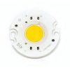
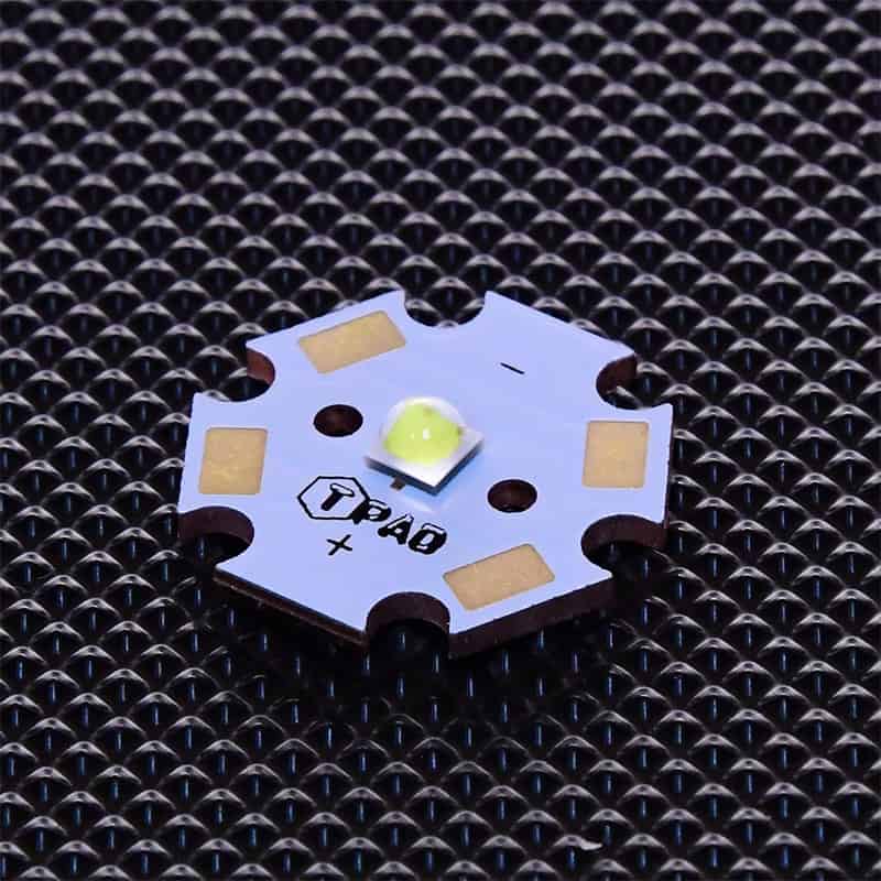
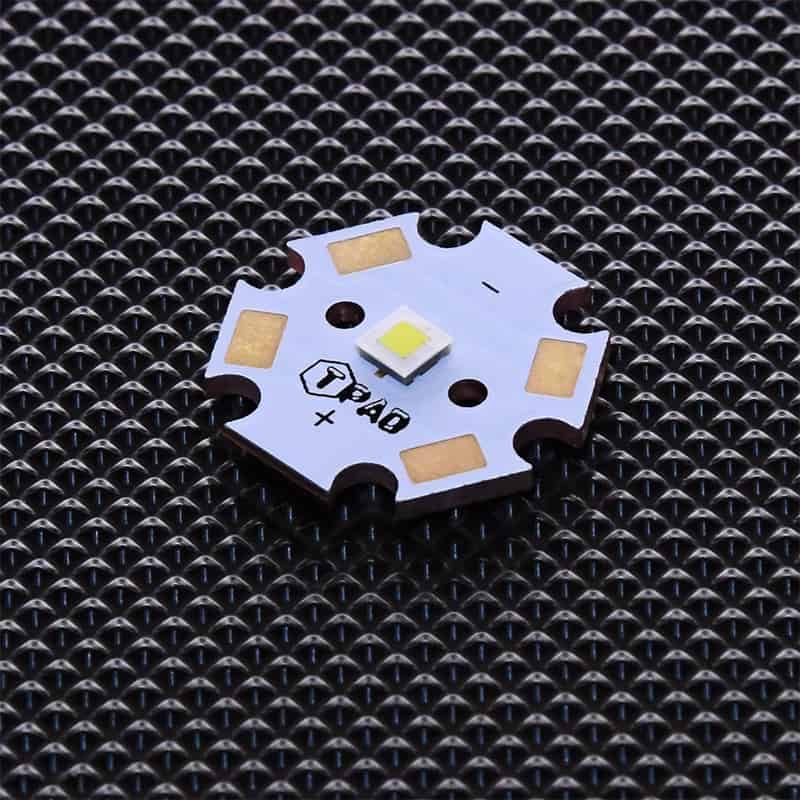
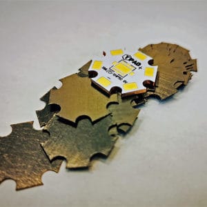
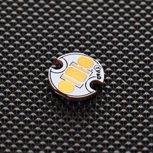
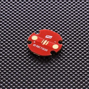
Copper Star shaped MCPCB for XP series, XT-E, 3535, 219. Direct Thermal path PCB, 20mm Diameter, 1.66mm Height
1894 in stock (can be backordered)
| Price Break Qty | Discounted Price |
|---|---|
| 1 - 9 | $1.60 |
| 10 - 49 | $1.52 |
| 51 - 100 | $1.39 |
| 101 - 500 | $1.20 |
| 501 - 1000 | $0.93 |
Description
 MCPCB-XP20-Star MCPCB is made in our TPAD Technology and uses the latest pillar design technology to minimise thermal resistance by eliminating the dielectric layer so that the LED thermal pad is soldered directly to the aluminium or copper base. This ensures the lowest possible LED junction temperature, resulting in increased LED life, light power output and overall reliability.
The MCPCB-XP20Star is designed to take 1 leds, with 3.45×3.45mm base, so will suit Cree XPG, XPG2, XPL, XHP35, Nichia NVSL219 and numerous other leds with the same base dimensions. The board layout is for a single Led
Direct Thermal Path and What is it?
There is no Dielectric under the thermal pad of LED.
FAQ. What is Direct thermal path PCB design, also known as pillar or thermoelectric separation design, is a type of circuit board design that utilizes thermoelectric materials or metal pillars to create a direct thermal path between the heat source and heat sink.
This design helps to dissipate heat more efficiently and effectively, reducing the risk of overheating and improving the overall performance and lifespan of the electronic device. The direct thermal path enables heat to flow directly from the heat source to the heat sink, without having to pass through multiple layers of the circuit board or other components, which can create thermal resistance and reduce heat dissipation. In the case of TPAD technology, it means the absence of a dielectric, possible because of the 3 Pad design of 3535 Leds
Pillar or thermoelectric separation design also allows for the creation of smaller and more compact devices, as it reduces the need for additional heat dissipation components such as heat sinks or fans. It is commonly used in high-power and high-heat applications such as power electronics, LED lighting, and automotive electronics.
The MCPCB-XP20Star module requires careful attention to mounting and cooling to ensure that the junction temperature of the LED is kept well below the maximum rating as specified in the LED documentation published by Led Manufacturers
For optimal cooling, we recommend that the module be mounted to a suitable finned heat sink (aluminium or copper) that is exposed to open air. The module can be mounted to a heat sink in various ways
- 20mm pressure sensitive, thermally conductive tape (Recommended)
- Thermal Compound: Requires the use of mechanical fasteners
Before fastening the module to the heat sink, ensure that the two mating surfaces are perfectly flat and clean in order to maximise heat transfer to the the sink.
The bottom of the LED MCPCB is electrically neutral, so it is not necessary to electrically isolate the base from the cooling surface.
Please note the use of Thermal Adhesives makes the PCB unlikely to be removed for servicing. Please consider this if removal of the board is desired as another TIM may be a better choice.
Optics Support:
The board is drilled to take Ledil pinned Optics and other optics with the same pin footprint*
Heatsink Options:
Termination:
The board has multiple pads in Cathode and anode to allow for wire clearance in multiple application
* some holders may require modifications to allow wire access to the PCB, Cutter assumes no responsibility for holder modifications
Specifications
| Part # | MCPCB-XP20Star |
|---|---|
| PCB Technology | Direct Thermal Path Copper |
| PCB type | 20 mm Star PCB |
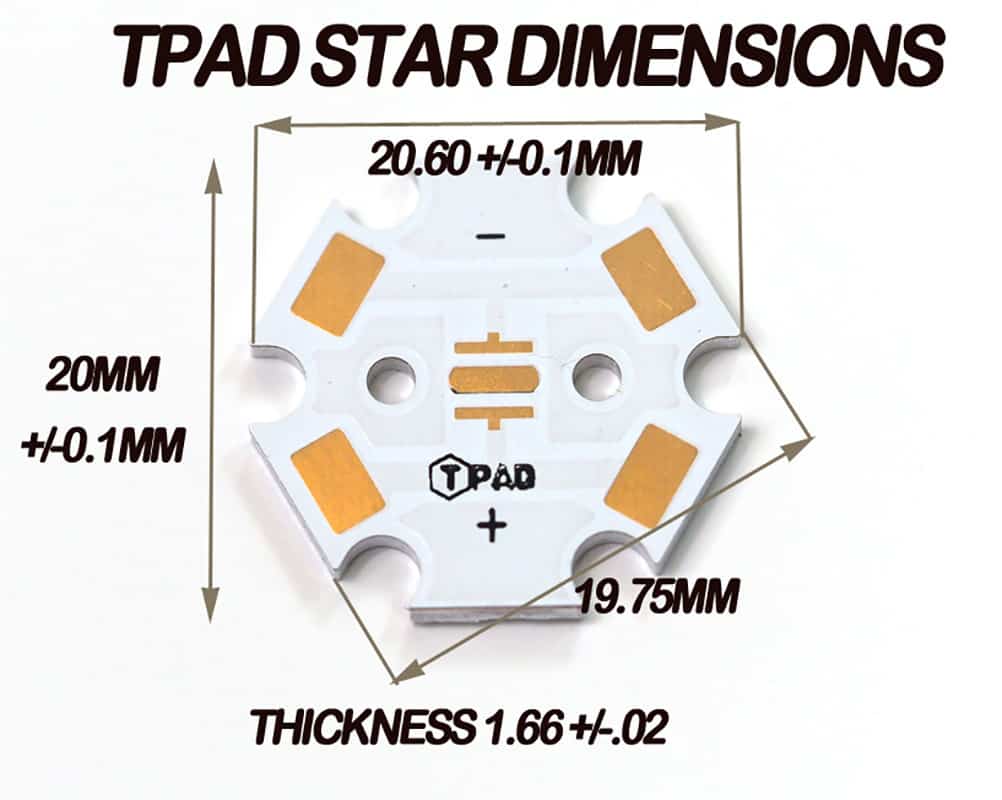
| PCB Size | 20mm x 1.65mm |
| Base Metal type | Copper |
| Finish thickness | 0.065”(1.65mm) |
| Direct Thermal Path | YES |
| Thermal Conductivity | 390.0 W/m.K |
| Surface Finish | ENIG |
| Glass Transition Temp. | 170 degree Celsius |
| Compatible LED | Cree XPG, XPG2, XPL, XHP35, Nichia NVSL219 |
| Weight | 0.03 kg |
|---|---|
| Dimensions | 20 × 20 × 1.7 mm |
| MCPCB Material | Copper Direct Thermal Path |
| PCB Size | |
| PCB by Led Type | |
| Thermal Conductivity | |
| Total Led Quantity per PCB | |
| PCB Solder Mask Colour | |
| PCB On Board Configuration | |
| PCB Material |
Brand
Cutter
Be the first to review “MCPCB-XP20-Star”
You may also like…
Related products


Reviews
There are no reviews yet.